Fcu Schematic Diagram Image Schematic Fcu
Coil fan hvac units fcu unit Image schematic fcu Schematic of control fcu with control signal.
How a Fan Coil Unit Works | HVAC Training Shop
Coil fan unit heat fcu diagram hvac cooling heating system cool air units exchanger piping successfully ac may simple commercial Image schematic fcu 3 speed push button switch for fan coil unit
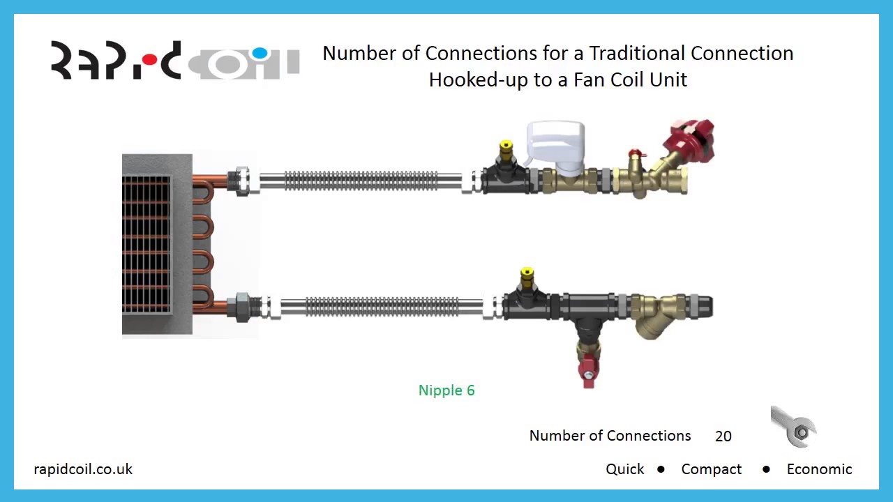
Fcu installation part 1 (connection details) (english)
Image schematic fcuSchematic of control fcu with control signal. Schematic of control fcu with control signal.Fcu schematic.
Smartstat- 2pipe fcu (fan coil unit) – 75f renatusImage schematic fcu Image schematic fcuSchematic of tested fcu water system.

Image schematic fcu
5: a fan coil unit(fcu) [11]Image schematic fcu Fan coil units fcu the engineering mindset, 49% offImage schematic fcu.
Fcu connection details with 3-way control valve.Image schematic fcu How a fan coil unit worksEsaplling pvt ltd: 'fan coil unit' (fcu)..!.
Fcu block diagram.
How fan coils work in hvac systemsImage schematic fcu Fcu valve connection installation hookImage schematic fcu.
2 schematic of a typical fcu acmv systemIcp das Image schematic fcuImage schematic fcu.

Image schematic fcu
Image schematic fcuFcu connection details installation Image schematic fcuFcu schematic.
Fcu and accu diagram [28 properties] (january 2024) on onepropertee.comFcu hook up .


2 Schematic of a typical FCU ACMV system | Download Scientific Diagram

How a Fan Coil Unit Works | HVAC Training Shop

Image Schematic Fcu

Image Schematic Fcu

Image Schematic Fcu

Image Schematic Fcu

FCU connection details with 3-way control valve. | Hvac design, Fan

Schematic of control FCU with control signal. | Download Scientific Diagram